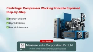
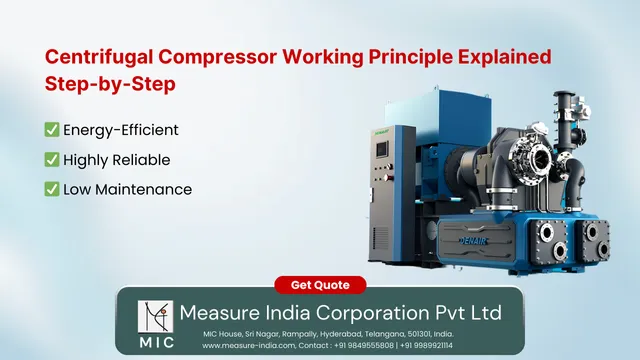
Centrifugal Compressor Working Principle Explained Step-by-Step
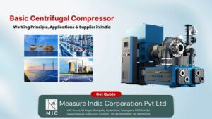
Centrifugal compressors are dynamic machines designed to compress air or gas using centrifugal force. Their working principle relies on the transformation of kinetic energy to pressure energy through high-speed rotating impellers and diffusers. These compressors are vital in industries such as oil & gas, chemical processing, HVAC, and power generation.
In this blog, let’s explore the step-by-step working principle, key components, and why centrifugal compressors are a preferred choice for high-volume applications.
What is a Centrifugal Compressor?
A centrifugal compressor is a radial-flow type dynamic compressor. It increases the pressure of a gas by converting velocity into pressure through mechanical action. Unlike positive displacement compressors (like reciprocating types), it provides continuous compression and is ideal for large flow rates.
Want to see the range? Check here:
Centrifugal Compressor – Measure India Corporation
Step-by-Step Working Principle of Centrifugal Compressor
Let’s understand the 4 primary steps involved in the working of a centrifugal compressor:
Step 1: Suction (Inlet)
Ambient air or process gas enters the compressor inlet.
Sometimes, inlet guide vanes are present to regulate airflow direction and quantity.
Flow is axial at entry and then turns radial through the impeller.
Step 2: Impeller – Velocity Addition
The impeller is the rotating part, typically driven by an electric motor or turbine.
As the impeller spins (often 10,000 to 50,000+ RPM), it imparts kinetic energy to the gas.
Gas is flung outward from the center (eye of the impeller) due to centrifugal force.
Result: High velocity, but still low pressure.
Step 3: Diffuser – Pressure Rise
High-velocity gas enters the diffuser section, which is a set of diverging passages.
Here, the gas slows down (velocity decreases), and pressure increases due to the conversion of kinetic energy.
This process is called isentropic compression (ideally), with minimal energy loss.
Step 4: Volute / Collector – Discharge
The compressed gas is collected in a spiral-shaped casing called the volute.
The volute helps in even distribution of pressure and delivers the gas to the downstream piping.
Want a machine like this? Check:
Centrifugal Air Compressors – Measure India Corporation
Major Components of a Centrifugal Compressor
| Component | Function |
|---|
| Inlet Guide Vanes | Controls incoming flow and angle |
| Impeller | Adds velocity to the gas |
| Diffuser | Converts velocity into pressure |
| Volute Casing | Collects and directs compressed gas |
Performance Characteristics
Pressure Ratio: Typically 1.2 to 3.5 per stage
Flow Rate: High, ideal for large-scale operations
Efficiency: Varies between 70% to 85%
Multi-stage Design: For higher pressure applications, multiple stages are used
Looking for industry-specific solutions?
Industrial Air Compressors – Measure India
Applications of Centrifugal Compressors
Oil & Gas – Refinery gas compression
Petrochemical Industry – Air separation, hydrogen compression
Power Plants – Combustion air for gas turbines
HVAC Systems – Chillers and air circulation
Food & Beverage – Clean air for packaging
Advantages of Centrifugal Compressors
Continuous, non-pulsating flow
Oil-free compression (when configured appropriately)
Fewer moving parts = Lower maintenance
Compact design for high flow
Better suited for clean environments
Limitations
Not ideal for low flow and high-pressure applications
Sensitive to surge and choke conditions
Efficiency drops significantly outside the design point
Requires precise balancing and design
Conclusion
The centrifugal compressor working principle is rooted in the transformation of energy — velocity added by the impeller is converted into pressure in the diffuser. These machines are efficient, reliable, and ideal for high-flow operations in critical industries.
Whether you are planning to upgrade your system or want a tailor-made compressor, explore our complete range:
Centrifugal Compressor
Centrifugal Air Compressor
Industrial Air Compressors